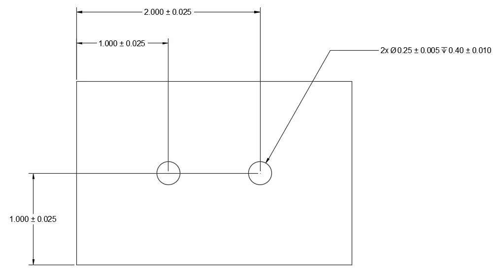
Blind Hole Callout. The annotation symbols for blind holes are shown in the following figure: The depth of the drilled hole is indicated after the diameter. the callout ⌀.098 ↧.200, for instance, specifies a hole with a diameter of 0.098 inches and a depth of 0.200 inches. The downward arrow symbol (↧) represents the depth to which the hole is threaded (tapping depth). here is an example of how to callout a blind hole for an engineering drawing: this article will explore what a blind hole is, how to make blind holes, and why they are essential in machining. Importance of hole placement and orientation. blind hole callout symbol in engineering drawing. The diameter of a hole is often indicated by an “o” symbol, followed by the measurement. Therefore, this callout symbol helps machinists and product engineers understand the design intent and accurate hole drilling. Tolerances, surface finish, and material considerations. the callout for a blind hole will include the following: Placement and orientation significantly impact stress distribution, machining tool access, and overall aesthetics. the callout symbol of a blind hole shows its desired location, thread pitch, fastener size, diameter, and depth specification on the engineering drawing. The callout ⌀.098 ↧.200 means a 0.098” diameter hole to a depth of 0.200”.
from www.machinistguides.com
blind hole callout symbol in engineering drawing. The diameter of a hole is often indicated by an “o” symbol, followed by the measurement. the callout for a blind hole will include the following: the callout symbol of a blind hole shows its desired location, thread pitch, fastener size, diameter, and depth specification on the engineering drawing. this article will explore what a blind hole is, how to make blind holes, and why they are essential in machining. Placement and orientation significantly impact stress distribution, machining tool access, and overall aesthetics. The annotation symbols for blind holes are shown in the following figure: The callout ⌀.098 ↧.200 means a 0.098” diameter hole to a depth of 0.200”. The depth of the drilled hole is indicated after the diameter. Tolerances, surface finish, and material considerations.
Blind Holes All About Machinist Guides
Blind Hole Callout The diameter of a hole is often indicated by an “o” symbol, followed by the measurement. the callout ⌀.098 ↧.200, for instance, specifies a hole with a diameter of 0.098 inches and a depth of 0.200 inches. The “φ” symbol indicates the actual diameter value of the hole. The depth of the drilled hole is indicated after the diameter. The diameter of a hole is often indicated by an “o” symbol, followed by the measurement. The annotation symbols for blind holes are shown in the following figure: Therefore, this callout symbol helps machinists and product engineers understand the design intent and accurate hole drilling. the callout for a blind hole will include the following: Placement and orientation significantly impact stress distribution, machining tool access, and overall aesthetics. Importance of hole placement and orientation. here is an example of how to callout a blind hole for an engineering drawing: Tolerances, surface finish, and material considerations. The placement and orientation of blind holes significantly impact the usefulness and manufacturability of parts. The downward arrow symbol (↧) represents the depth to which the hole is threaded (tapping depth). this article will explore what a blind hole is, how to make blind holes, and why they are essential in machining. the callout symbol of a blind hole shows its desired location, thread pitch, fastener size, diameter, and depth specification on the engineering drawing.